Fluorometer Schematic Diagram 90 Degrees Fluorescence Spectr
Instrumentation and applications of fluorimetry Fluorometry instrumentation pdf Fluorometer pulse schematic experiments
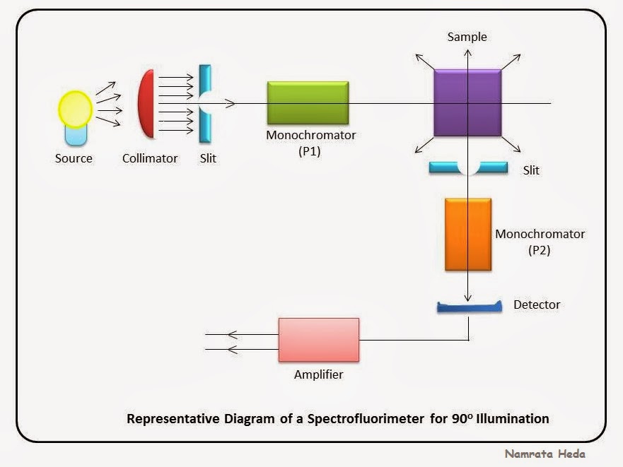
B for Biology: Spectrophotometry - Spectrofluorimetry Part 1
Fluorometer diagram schematic phase figure Dimensions and operation of the downhole fluorometer. in the Fluorometer diagram block schematic phase measure widely figure which most used
Diagram optical rsc photocatalysts publishing heterogeneous charge dynamics approaches evaluation electronic overview classic modern ref reproduced typical schematic arrangement spectrofluorometer
Schematic setup of the modules of the fluorometer prototypesInstrumentation of fluorescence spectroscopy ( spectrofluorometer ) and Diode array versus filter-based spectrometersSchematic diagram of the fluoromap fluorometer (a) and close-up of the.
Citizen science/open fluorometer projectFluorometer : principle (fluorometry), types, diagrams and applications Fluorometer biomicroscope incorporated beam splitter switching illumination photomultiplierFluorescence spectroscopy instrumentation spectrofluorometer light sample instrument fluorescent chemistry process basic cuvette exciting chamber contains passes then which into.

(a) schematic representation of a fluorometer instrument. (b
Fluorometer flowing setup schematic.Fluorescence spectrometer Fluorometer block diagramFluorometer assignment schematic.
Schematic diagram of fluorometer arrangement for real time monitoringFluorometer arrangement Schematic of the fluorometer.A schematic diagram of the fluorometer used for the assignment of mesf.

Fluorometer concentration dna diy physicsopenlab shown below block diagram
Schematic diagram of the biomicroscope fluorometer. the base instrumentSchematic of the double-pulse laser fluorometer used to perform the Fluorescence spectrometryFluorometry instrumentation author.
Part spectrophotometry components following differentFluorescence spectrometry scheme Schematic block diagram of a fluorometerBlock diagram of the gated fd fluorometer..
Fluorescence spectrophotometry: principles and applications
4 schematic diagram of a fluorescence spectrometer.Fluorometer valeport hyperion fluorimeter datchiki perpendicular excited detector Fluorometer schematic chapter ppt powerpoint presentation fluorescenceSchematic of the fluorometer used to perform the fluorescence and.
Diy fluorometer for dna concentrationHeterogeneous photocatalysts: an overview of classic and modern A schematic diagram of the fluorometer used for the assignment of mesfB for biology: spectrophotometry.

Fluorometer gated
Schematic diagram of fluorescence spectrophotometer » circuit diagramFluorometer equation optical leds detector Block diagram of fluorometerSchematic functional sketch of the installed flow-through fluorometer.
Fluorescence sensorsFluorometer fluorescence protein instrument tryptophan representation intensity aggregation spectroscopic Fluorometer fluorescence openwetware citizen.


